VR
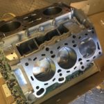
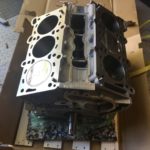


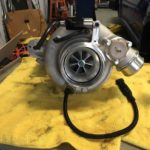
Look what the truck man brought me. Time to turn stupid up to 11. VR38DETT, 1000whp, no traction.
Look what the truck man brought me. Time to turn stupid up to 11. VR38DETT, 1000whp, no traction.


For my fellow OCD nerds;
I learned a good lesson in always digging into the small stuff if it seems odd. I have been collection some thermocouple, thermistor, and pressure data in one of my cars using a RaceCapture Pro data acquisition device. It can record 7 channels of analog data along with a bunch of internal sensors including GPS, acceleration, rpm, and some CAN messages. I recently added an oil temp and oil pressure channel and have been looking at the data. I noticed that on startup the oil temp didn’t match the coolant temp nor the cylinder head temp. If the engine were running one might expect those to be different, but after a night of settling they should have all reach equilibrium. It wasn’t a huge error, but still concerning.
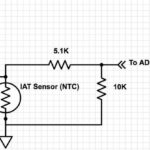
The oil temp sensor is a NTC sensor (Negative Temperature Coefficient), so it has variable resistance based on temperature. In this case the resistance would vary from about 180 ohms to about 200k ohms over the useful range, with a resistance at 25C of 11k ohms. The analog inputs of the RaceCapture are designed for 0-5V sensor, so I used a simple divider (show below) to attach the sensors. It uses a 1K pullup to +5V, allowing the RaceCapture to infer resistance from the incoming voltage. My first thought was that I had made a mistake in the calibration table, but that checked out fine. I unplugged the sensor and directly measured the resistance, and used that resistance to look up a temperature from the data sheet. That temperature matched the temperature I measured with my FLIR camera, so the sensor seemed fine. I plugged everything back in and measured the sensor output voltage going to the RaceCapture, then compared that to the calibration data. It was wrong, and that explained why I was getting incorrect readings. I then checked the +5V output from the Racecapture and sure enough it was 4.6 volts. I took a look at the schematic for the RaceCapture and that 5V output is only intended to be used as a reference with very low current draw. All of my sensors were pulling down the output to 4.6 Vs.
In some designs this would have been less of a problem if the Analog to Digital converters used this same ‘reference’ output for the ratiometric reference. There would still be a small error, but much much less. It turns out the Analog inputs in the RaceCapture don’t use that external 5v reference internally as a reference. The fix was to grab a TSR2540 from my workbench and make a small PCB to give me a higher current stable 5V reference I could use to power the sensors.
After getting that installed the readings improved, but there was still a bit of error. I took a look at the schematic of the RaceCapture again, and there it was. The analog inputs were going thru a voltage divider before going into the processor, and that voltage divider was causing additional voltage drop due to the low input impedance.
The designers used a 5.1K and 10K divider to lower the input signal from 0-5V to 0-2.5Vs, but by using such low resistance it drops the voltage more then 2:1 when the output impedance of the sensor is high. The fourth schematic shows the effective circuit that the sensor sees. If we assume the ADC input in the processor is very high impedance (which it probably isn’t) you have an effective 15k in parallel with the sensor resistance. If the sensor resistance is very high, say 20k ohms, the resistance as inferred at the ADC would actually be only 8.5K.
The right way to interface a sensor like this is to use an Opamp, which would have made the analog inputs of this device much more useful in cases like this. Other sensors that have direct voltage output with sufficiently low output impedance would not have a problem with this kind of input design.
I can correct for this design error in the calibration tables, so I can still get everything working, but it was an interesting exercise. In my own CAN based ADC interface (in design and test right now) I am using dedicated opamp drive and filtering which we provide better input isolation for situations just like this. It is a good reminder to always plan and test the calibration of your equipment, and understand how it works.

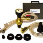
Two tools I really really really love. A kickin flare tool, and a vacuum coolant system filling tool. Gone are the days of the burp and the coolant leaks.


In the past I have used the AEM exhaust backpressure sensor kit, which works well. It is about $250 (AEM 30-2064), and includes one of their stainless steel 100psi sensors, as well as a few parts to help cool the exhaust charge before it gets to the sensor. You can also build up the same parts for a bit less cost. I ordered the following parts from McMaster-Carr to make up my own kit:
2x 5482K75 Precision AN 37 Degree Flared Tube Fitting, 304 Stainless Steel Nut for 1/4″ Tube $3.50 each.
2x 5482K82 Precision AN 37 Degree Flared Tube Fitting, 304 Stainless Steel Sleeve for 1/4″ Tube $1.40 each.
1x 5482K111 Precision AN 37 Degree Flared Tube Fitting, 304 Stainless Steel Adapter for 1/4″ Tube OD X 1/8 NPT Male $9.76 each
1x 5482K32 Precision AN 37 Degree Flared Tube Fitting, 304 Stainless Steel Straight Connector for 1/4″ Tube OD $11.02 each
1x 50715K171 Type 316 Stainless Steel 37 Degree Flared Tube Fitting, Straight Adapter for 1/4″ Tube OD X 1/8 NPT Female $9.18 each
1x 4468K811 HT-Pressure Braided Chemical Hose with Fittings, Brass 7/16″-20 Flare UNF Female, 3/8″ OD, 12″ LG $15.49 each.
1x 89895K722 Smooth-Bore Seamless 304 Stainless Steel Tubing, 1/4″ OD, 0.02″ Wall Thickness, 3 ft. Long $18.33 each.
Total cost for parts for a single sensor setup (not including the sensor) was $73.58, plus about $8 shipping.
For a sensor you could purchase the AEM sensor for $152 for a total kit cost of $234, just a tad cheaper than the $250 AEM kit.
However I am using a Honeywell Stainless steel sensor (PX2AN2XX100PAAAX) that is almost the exact same design, but $80 for a total cost of $163. The Honeywell Stainless steel sensors are a great replacement for the AEM ones, in part because AEM doesn’t make the sensor, they just rebrand it from someone like Honeywell. You can get the Honeywell sensor in the same 3 pin Metripack connector, or the more robust Deutsch DTM.
You could also make a cheaper kit by not using all Stainless steel parts. The AEM kit for instance doesn’t use a stainless steel -4 to -4 male connector, and one of the two NPT parts isn’t stainless steel. I prefered to use all stainless parts to prevent corrosion in a part with very high heat and exposure to road water.


Did a little regatta today in Boston Harbor. Fun, but would be more fun with 1000hp.

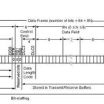
Hmm.. so continuing on my investigation of the idea Mike Innovative McGinnis mentioned, using a CAN bus interface for all of the data collection and transmission. That would allow me to use an aftermarket logger (Motec, RaceCapture, etc). The fastest supported CAN speed in most of these products is 1Mhz. A normal extended CAN packet is 128bits, plus 3 interframe bits. Since CAN is NRZ, it has to do padding with long strings of zeros, so worst case packet size is 140 bytes plus 3 interframe bits. A packet transmits 8 bytes, so for simplicity assume that is 4 sample channels. For 24 channels I would need 6 frames. At 1 MHz you could get a theoretical framerate of 6993 frames per second, which would be 1165 samples/sec. Piratical limits would be less then this.
This can work, but is really close to the limits of CAN. I have doubts that any of the loggers can handle data at that rate as well. I could lower overall capture rates to either 500hz or 100hz, and certainly things like temp sensors don’t even need that high of a datarate. Perhaps I’ll create three classes of capture channels and set the rates accordingly. The real question is what type of CAN messages can these guy decode? Can you specify MSB/LSB, Conversion factors? Up next are some question to Motec and a few other vendors.


So, now that I have a ton of signals that need capture, I need to tackle the data acquisition problem. I could use an off the shelf solution, but in looking for something that can do 24+ channels of 12 bit 1000hz capture, plus some digital mode capture, I am looking at $5-6k. AIM, Traq, RacePaq, Motec, etc. Sure those are well engineered solutions, but this is kids play in the data acquisition world. I worked on a system for aircraft engine controls 30 years ago that was much faster and more accurate than this needs to be.
I have a previous design that I can make work, but it is kludgy.
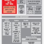
Here is what I am thinking: In the past I have used a variety of microcontrollers for the primary capture. It works well, but in the modern era is seems dated. There are so many choices in platform that have so much more processing power. My previous capture system used a TI ARM based processor which had plenty of horsepower but the system dev tools were convoluted. TI-RTOS works, but I really don’t need a system like that. For this design I’m thinking of using something much faster and simpler to develop for: A Beaglebone Black. The Beaglebone Black has a 1GHz ARM processor, 512MBs of RAM, and a plethora of peripherals. Best of all, it runs Linux, so many of the interfacing and use problems are already solved. I can have Wifi and Bluetooth for automatic data downloads, display interfaces, wireless development, tablet and phone interfaces, and more. I wouldn’t use the Beaglebone Black’s built in ADCs, but since it has plenty of SPI interface capability I would use external ADCs. The Beaglebone supports external boards called capes, but I’m thinking of making a larger board that would hold the Beaglebone, sort of a reverse cape. On that board I would put the analog interface circuitry, power regulation, connectors, etc.
For the ADCs I’m thinking of either the MCP3208s or the MAX146s. Both have 8 channels (So I would use 4x of them), SPI interface, 12 bit resolution, and in the case of the MAX146 a built in 2.5V reference. For the analog input section I’ll use a divider with schottky diodes for protection fed into an MCP601 single supply opamp configured as a Sallen-Key active low pass filter with unity gain. (test schematic attached) That would provide the needed input impedance from the sensors, as well as the output impedance for the ADCs. One nice thing about this setup is the diode protection doesn’t cause linearity problems in the sampling because the ADC reference is 0-2.5V, while the diode protection is from -.6V to about 3.8Vs.
I was worried a little about using the Beaglebone for the SPI communications, since the timing of those packets determines to timing of the actual analog sampling. With 32 channels at 1000hz I need 3 SPI transfer cycles per sample which would be 96000 transfers per second, which is easy over SPI. These ADCs are both capable of sample times of less than 10us, which could net about 90 sequential channel grabs per 1ms (1000hz). In reality I could run some things in parallel, and get better performance, but I don’t think it is needed.
The Beaglebone processor also as 2 PRU cores integrated into the die. These are like small 32 bit microcontrollers that can be use for offloading time sensitive interface problems. I might use one of these to do the SPI interfacing and timing, since that could enable a continuous stream to the main processor regardless of what the OS is doing.
Since I have a Beaglebone Black as well as one of the ADCs already, I’ll put together a prototype and see how well it works. I would love to hear any comments/concerns/refinements from my fellow engineers and the like.
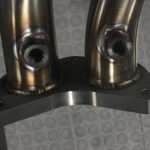
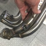
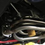


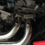


Thanks to Jeff Perrin for adding some bungs to a new Perrin manifold for my 08 STI test car. I’m adding some new sensor elements to help with collecting test data while I’m in there changing turbos. I’ll have real time logging of:
Oil Pressure from 2 locations
Oil Temp
Fuel Temp
Fuel Pressure
Coolant Pressure
Coolant Temp
Pre Intercooler Post Compressor Temp
Pre Intercooler Post Compressor Pressure
Post Intercooler Temp
Post Intercooler Pressure
Pre Compressor Temp
Pre Compressor Pressure
Compressor Wheel Speed (EFR8374)
Exhaust Gas Back Pressure Pre Turbine
Exhaust Gas Back Pressure Post Turbine
Exhaust Gas Temperature for each Cylinder (4x)
Exhaust Gas Temperature Post Turbine
AFR Pre Turbine
AFR Post Turbine
Cylinder Pressure via Optrand Optical Sensor
Cylinder Head Temperature
High Speed Crank Sensor Measurement
Wideband Knock Sensor with spectral analysis
Antimatter-Matter Interaction Sensor with Dilithium Crystal Substrate (ok I made that one up)
as well as all of the usual ECU measured stuff.
Anything obvious I am missing?