ADC


For my fellow OCD nerds;
I learned a good lesson in always digging into the small stuff if it seems odd. I have been collection some thermocouple, thermistor, and pressure data in one of my cars using a RaceCapture Pro data acquisition device. It can record 7 channels of analog data along with a bunch of internal sensors including GPS, acceleration, rpm, and some CAN messages. I recently added an oil temp and oil pressure channel and have been looking at the data. I noticed that on startup the oil temp didn’t match the coolant temp nor the cylinder head temp. If the engine were running one might expect those to be different, but after a night of settling they should have all reach equilibrium. It wasn’t a huge error, but still concerning.
The oil temp sensor is a NTC sensor (Negative Temperature Coefficient), so it has variable resistance based on temperature. In this case the resistance would vary from about 180 ohms to about 200k ohms over the useful range, with a resistance at 25C of 11k ohms. The analog inputs of the RaceCapture are designed for 0-5V sensor, so I used a simple divider (show below) to attach the sensors. It uses a 1K pullup to +5V, allowing the RaceCapture to infer resistance from the incoming voltage. My first thought was that I had made a mistake in the calibration table, but that checked out fine. I unplugged the sensor and directly measured the resistance, and used that resistance to look up a temperature from the data sheet. That temperature matched the temperature I measured with my FLIR camera, so the sensor seemed fine. I plugged everything back in and measured the sensor output voltage going to the RaceCapture, then compared that to the calibration data. It was wrong, and that explained why I was getting incorrect readings. I then checked the +5V output from the Racecapture and sure enough it was 4.6 volts. I took a look at the schematic for the RaceCapture and that 5V output is only intended to be used as a reference with very low current draw. All of my sensors were pulling down the output to 4.6 Vs.
In some designs this would have been less of a problem if the Analog to Digital converters used this same ‘reference’ output for the ratiometric reference. There would still be a small error, but much much less. It turns out the Analog inputs in the RaceCapture don’t use that external 5v reference internally as a reference. The fix was to grab a TSR2540 from my workbench and make a small PCB to give me a higher current stable 5V reference I could use to power the sensors.
After getting that installed the readings improved, but there was still a bit of error. I took a look at the schematic of the RaceCapture again, and there it was. The analog inputs were going thru a voltage divider before going into the processor, and that voltage divider was causing additional voltage drop due to the low input impedance.
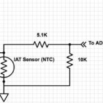
The designers used a 5.1K and 10K divider to lower the input signal from 0-5V to 0-2.5Vs, but by using such low resistance it drops the voltage more then 2:1 when the output impedance of the sensor is high. The fourth schematic shows the effective circuit that the sensor sees. If we assume the ADC input in the processor is very high impedance (which it probably isn’t) you have an effective 15k in parallel with the sensor resistance. If the sensor resistance is very high, say 20k ohms, the resistance as inferred at the ADC would actually be only 8.5K.
The right way to interface a sensor like this is to use an Opamp, which would have made the analog inputs of this device much more useful in cases like this. Other sensors that have direct voltage output with sufficiently low output impedance would not have a problem with this kind of input design.
I can correct for this design error in the calibration tables, so I can still get everything working, but it was an interesting exercise. In my own CAN based ADC interface (in design and test right now) I am using dedicated opamp drive and filtering which we provide better input isolation for situations just like this. It is a good reminder to always plan and test the calibration of your equipment, and understand how it works.