CAN


Here is a quick video about the dev environment I’m using for the
CanADC module.
A pic of the board with the FLIR camera as well.
Here is a quick video about the dev environment I’m using for the
CanADC module.
A pic of the board with the FLIR camera as well.
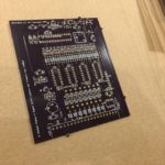


My second prototype PCBs arrived today. I populated the analog sections and tested the amps and filters. Everything looked great. I finished up the digital sections, flashed on my new firmware, and got blinking lights. And CAN output at 100hz from all of the analog channels. 🙂


I’m facing an interesting dilemma. I have a 20 conductor cable (that I built) going into the cabin on my STI, intended to connect to the DAQ system. It goes to the engine bay and terminates in a 20 pin Deutsch HDP connector. From that I need to run to 18 different sensors, where each sensor has a sensor output, plus power and ground.
Option 1: I could do it like an OEM factory harness would work.. I would have one or two power and ground wires going around the engine as well as the signal wires, and at locations close to the sensors the signal wire would connect, and the power and ground would have a tap. This would be your typical black tape wrapped around plastic split loom tubing. The plus side is the ease of building, but once it is done and all wrapped up, it takes some work to add more sensors, or change the location of a sensor. It also means a bunch of splices in the 5v and ground wire. Another minor issue is that I need to add some 5V pullups for some of the sensor, so that would have to but put in the harness as well.
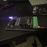
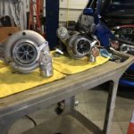
Option 2: I could make a custom PCB like I did for my GTR. (See picture 2 and 3). In that case the PCB had the pullups, plus the +5 and Ground aggregation. I used PCB mount screw terminals, then I then connected to HDP connectors. This solved the multiple things needing connection to a single 5V and GND wire. I could even skip the HDP connectors on the sensor side, and have each sensor wire connect right into the terminal blocks. In this way every sensor connects back to one place.
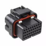
Option 3: I could make a new PCB and case, but using something like the EN3(or M8, or Micro-Con-X) connector in picture 4. That is similar to how the AIM Dash sensors are connected. For 18 sensors I would need 18 of these, which would be a difficult fit in a single panel. I’d probably need 2 or 3 panels with these connectors on them, all aggregating down to the 20 pins HDP connector. The advantage of this setup is each sensor cable is just a plug-and-play fitting that can be moved, replaced, etc.
Any thoughts?
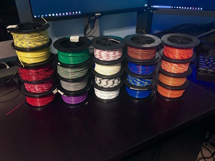
I really like Prowireusa.com. Lots of choices of colors for their M22759/32 Tefzel wire. I’m a strong believer in having all wires in a single harnesses with unique colors… Or at least unique per connector. I remember looking at one of the ECU harnesses on my GTO (LS2), and sure enough one ECU connector had 3 different unrelated circuits with the same color wire!
So.. 21 wires per harness is my limit right now. Need to get some more colors.


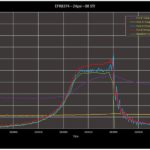

And a bit more data.. Here are three graphs at different boost levels. Wastegate, 22.5psi, and 24psi. Red and Blue show pre and post intercooler pressure levels, purple and yellow show pre and post intercooler temperatures, and green manifold pressure.
A few interesting observations: The Intercooler is working very very well. You can see the rise in temperature going into the intercooler going as high as 240F, but air temp coming out is just 10 degrees above ambient. This efficiency would certainly change with more time at high boost. Overall output temperatures at this boost level is very good. I was seeing about 50 degrees F hotter with the 7670 at the same boost level.
Pressure post intercooler, but pre throttle body is the most variant. I suspect that is related to the convoluted path, as well as the throttle body disruption. It is interesting to see that to get manifold pressure of 24psi, the turbo is pushing out at almost 28psi.
The fourth graph is a zoom in of the pressures post bypass valve opening event. In this setup the bypass valve is on the turbo itself, which is pretty far away from the closing throttle plate. You can see the oscillations as the pressure wave moves from the throttle plate, through the intercooler, and to turbo outlet. That looks to be about 9Hz, and I would assume that frequency is correlated to the length of pipe between the two end points. The post intercooler signal is stronger, which makes sense giving the damping from the intercooler.
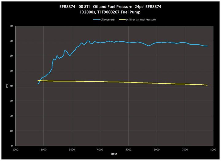
Now that I am getting my DAQ setup on the STI, I’ll have some more data to look at. Here is a graph of oil and fuel pressure by rpm. Oil pressure is pretty constant up to the redline of 7800, with just a bit of dip from 7200rpm up. I would normally want slightly higher pressure, but I’ll take constant pressure over dropping pressure at higher RPM. This is 15w40 oil, and the oil temp was about 210F. Oil pump is a factory 11mm STI unit, and engine rod bearing clearances around .0019 to .0025. This motor is one I built in the garage back in early 2013. The dip in oil pressure at 5700 rpm corresponds directly with a significant change in intake and exhaust AVCS, which are oil pressure controlled. Interesting. Oh and this is oil pressure measured at the back side port of the block.
The yellow line is differential fuel pressure, with an idle value of about 43.9psi. Ideally you would want that line to be perfectly flat, but as Lance Lucas said, ‘if we only had an infinitely long spring!”. It drops about 2.8psi over the entire pull, and this is with about 69% peak duty cycle. The pump is a single Walbro 450lph E85 pump in a Radium surge tank. (Direct wired power) I suspect it will fall quite a bit more at higher duty cycles, so I’ll probably jump to a bigger twin pump setup.
Both of these graphs look good, which is probably related to why the car is still running after 3+ years of automotive debauchery with the old EFR7670.
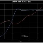
Spool up on my new EFR8374 isn’t too bad. Given this is a 79lb/min turbo (similar to a GTX35R), it is certainly acceptable. It doesn’t feel that much laggier then the 7670 I ran before. This is 3rd gear, Internal wastegate, 2.5L with Cosworth heads and cams, E85. Peak injector duty cycle was 69%. [ID2000s] Time to turn it up to 35psi.
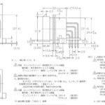


I’m working on the physical design for my 24 channel 1000hz ADC-CAN device. For the connector, I’d like something with 30+ pins, weatherproof, and reliable. I’m thinking of use the TE plugs that are commonly used by Motec, Link, etc. I have crimper for them, as well as a bunch of pins and a few of the female plugs. They make nice edge mount 90 degree PCB connectors, so it is pretty easy to design around. Any comments on these? I suspect John Reed might have an opinion? They are reasonably priced (perhaps $15 for the PCB connector) and are easy to get.
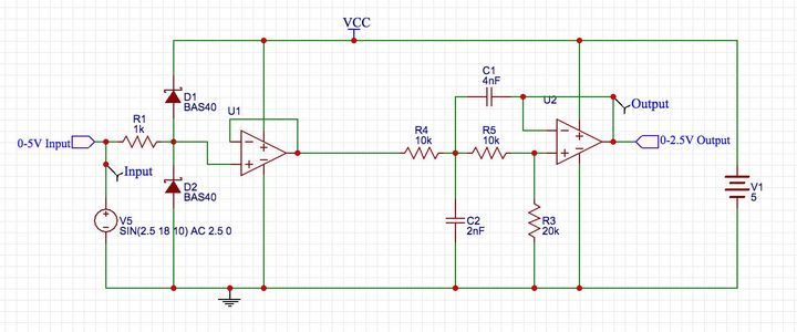
Fellow data nerds – Just looking to see if there is anything obvious I am missing. This is the analog input stage for my 24 channel ADC to CAN device. This is from a Spice simulation, so V1 represents the 5V supply, and V5 a simulated 0-5 signal. Here is my thinking: R1 is a current limiting resistor for the two Schottky diodes. They will conduct if the input voltage is over 5.3V or below -0.3Vs. That provides basic input protection ( hooking input to 12Vs, etc). U1 is an isolation op-amp to provide high input impedance. R4,R5,C1, and C2 make up a Sallen-Key filter, and R4,R5, and R3 make up a voltage divider. Combined with U2 this gives a 2:1 voltage division, and provides output impedance isolation to the ADC. The filter is set for a 3db rolloff around 2khz, which is good considering I only need to support 1khz sampling. For an Op Amp I need to use a single supply rail-rail variety like an OPA342. Since you can get those in 4x packages, I could do two input channels per chip. Let me know if it looks like I missed anything obvious.