Cloud

Cloudy vs clear days. Peak production of 9.32kw, almost 39 amps at 240Vs.
I did a little more looking at the treeline at the new house, and I think I can fit 10kws of panel that will have enough exposure.
Cloudy vs clear days. Peak production of 9.32kw, almost 39 amps at 240Vs.
I did a little more looking at the treeline at the new house, and I think I can fit 10kws of panel that will have enough exposure.

Hmm… With a rough look at power needs in the new house, I think 400A will cover it, but it is close. The main panel is subscribed about 1.65:1, which is typical with lots of high load devices. I am sure I am missing another 50A in there.
The non generator panel is subscribed 1.8:1, but whatever chargers I use I suspect they will support load communication (so they can share circuits).
The welder circuits are also shared with one of the tesla circuits in the lower garage.


Let’s talk about driveway lights. My driveway will be about 1000 ft long, winding through trees ( picture shows current condition, but once the house is complete it will be paved with a 12-14 ft wide driveway.)
I want lights along the driveway on both sides, which is pretty normal stuff.
However, I want each light to be individually addressable. I want to be able to control each one individually, at a reasonable quick rate. The idea is to combine that with some motion detection and perhaps some computer vision to have the lights follow you as you drive in.
Also, it would just be cool to have phase in and out in some pattern. [ Note I did consider that I would not want this to look like a runway. I’ll use a light design that doesn’t have upward projection ].
Here is what I am thinking – looking for feedback. This sounds like something that Clay Cowgill and Christopher Neil Bradley might have done in the past.
The lights themselves could be either 12V or 120V lights, or perhaps some kind of multi-color LED light. At each light I would have a small device that can be addressed and can execute some code to control that specific light.
Power is straight forward as I can run an underground 120V power line which will not have significant drop over that distance given the small power draw.
For signaling and communication, I was thinking of two different paths – One is to use a simple RS485 bus, which can go that distance and support the number of nodes. That can be done over a single CAT5 cable.
A second idea would be to use a small ESP32 based board running Bluetooth LE Mesh. Each board would be capable of relaying to the next, especially at those distances.
I prefer the wired solution, but am happy to consider other ideas.
Let’s assume one light every 10 feet, so 200 lights total.


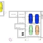
Since we are getting closer to build time, I need to sort out some things in my garage/shop area. I’m starting on the electrical plan, so it would be good to know where major things are going to be. This is what I have so far.
It looks like I could reasonably park 12 cars. The floor of the 4 car garage area is 4 feet higher than the shop ( due to the slope of the ground ), so the ceiling in the garage is 10.5′, and the ceiling in the shop is 14.5′.
I think a 10.5′ ceiling in the 4 car garage will be high enough to do one pair of 4 post storage lifts.
The upper garage turned out longer than I expected at 36″. Total garage/shop sq ft is ~3150.
Comments and Suggestions welcome!


Most of you know I have an M35, which is a rather large vehicle. Now I have an equivalent on the other side of the scale! And it is JDM!
I should put the IPV6 plate on the M35 and IPV4 plate on the Kei.


I flew my drone at our new house location today. We are filing for permits tomorrow, so the process begins!
It would appear that we will be tree huggers.


Since I had the 2.5L engine out of the 08 STI, I figured I might as well take it apart. I will re-assemble it with new bearings and use it in that 02 Bugeye I got a few months back.
This 2.5L motor is one that I assembled in my shop back in 2011. I ran the EFR7670 on it for most of that time, and switched to the EFR8374 last summer. On the 7670 is was running at 30psi, and about the same on the 8374.
Overall condition was not bad given the abuse and time ( 7 years ). The bearings are ACLs that were coated (Calico Coatings). The main bearings are smooth to the touch with no grooving that you can feel, but the coating is worn off in a number of places. A few lines from some contamination, but not enough to break the bearing surface.
The rod bearings have the typical wear pattern from a subaru, with the thrust half worn heavier on one side. The coating was pretty warn off on all 4 sets on the sides, and some contamination on the #4 bearing. Crank does not have any significant wear, but worth some polishing and balancing before rebuild.
The rods are a the rare Cobb rods. Not seen in the wild very much. 😉
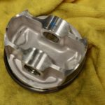
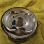
The pistons are the most surprising.. they look fantastic for pistons that have been running for 7 years at high boost levels. Very little skirt wear. I’ll measure everything before assembly, but you can certainly see the effect of water injection on the crowns. If everything measures up, I’ll get new rings and bearings and build it back up and send it again.
I was messing around with my drone again while Audrey and her cousins were playing. I still suck at it, but the music is nice.


Audrey decided if I was going to wash a car, she should have a picnic. She could have setup in the grass, but insisted the driveway was better. I think the grass looks pretty darn comfortable.

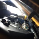

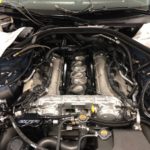
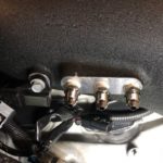
I decided to make some improvements in the EGBP measurement system in the GTR. I had some problems with the Honeywell PX2 sensors I had installed in the baffle cans. The location was certainly hot, and there was a direct heat path from the exhaust ports to the sensors.
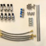
To improve the measurements I am doing two things:
First, I am moving the sensors from their location at the back of the engine to the sides of the engine bay, connected to the baffles with stainless softline and a small amount of stainless hard line. Second, I am replacing the sensors. The Honeywell PX2 sensors use a ceramic element, but the Honeywell MLH sensors have a Haynes 214 alloy element, which is a very oxidation and heat resistant material. [ As an aside, Haynes 214 is an interesting material, being an alloy of nickel,chromium,aluminum, and iron. My father spent most of his career at Haynes, so I heard lots about their alloys throughout my childhood!]