House

House

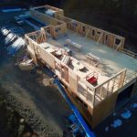
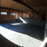
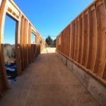
A few more snow days last week plus some really cold and windy days make for hard work, but more walls are coming into form! The shop is mostly complete in terms of framing, with the exception of the small bathroom I added. That will get framed a bit later. The middle level outside walls are getting built now, and the rear deck framing will happen next before doing the two story main level walls.

The windows have also arrived, but are in storage. As soon as we get framing done we will get the windows and the roof on so we can seal things up.

The Glulams for the deck were also delivered. I didn’t notice in the plan that all of the ‘floor joists’ under the deck are 3.5″ x 13.5″ x 22′ glulams. 40 of them. One glulam of that size at 22′ long should support around 320lb/linear foot or a total load of 7000lbs. Given there are 40 of them that is 280,000 lbs of load, which seems like a lot, even with the covered portion. Well engineered I think.

Com

Com

I have found the implementation of full duplex asynchronous high speed comm channel over a very synchronous master only SPI bus to be an interesting challenge. This is for my CAN logging device that uses a PiZero connected to a dsPIC33 over SPI, and the dsPIC33 connected to two 1mbit CAN busses. Since the PI has to be the SPI master, it controls the rate and timing of when things can be ‘sent’ to it from the Pi. I implemented a GPIO signal from the PIC to the Pi to indicate the desire to transfer, and while that works, the desire to have that transfer independent of what is actually being sent in the other direction adds some challenge. On top of that to sustain the full SPI data rate while having both CAN busses receiving and transmitting at full rate requires the use of the TX and RX SPI FIFOs, which really adds some interesting complexity. Since the FIFOs need to be full before we know what is coming from the other side, it requires some padding and packet ‘encapsulation’. After many tweaks and tests, I was successful in transcribing a over 10 million packets at full rate with a 100% loaded CAN bus over the SPI bus as well as the second CAN bus without dropping anything, and with only a 20% padding rate. I think for the next rev I am going to switch up to a dsPIC with more memory (this one only has 8k of RAM), so I can afford a bit more buffering.

In practice this really is a worst case, as typically there would be filters in place so you are only logging things from data devices, and eliminating things like status and clocking traffic.

SPI

SPI

I worked a bit on the SPI interface last night between the PI Zero W and the dsPIC33. The PI SPI interface really only supports being the master, so I am using a GPIO from the dsPIC to tell the PI if there is data waiting. In the PI world the default IOCTL interface to the SPI means a kernel call for every byte transfered. Using that method with a 1MHZ SPI clock I was getting an effective transfer rate of around 400Kbit, and even when jumping the SPI clock to 5MHz the effective rate was still less than 1mbit due to the calling overhead. Going direct to the memory mapped peripherals made a big difference, and now I can run as high at 62MHz SPI speed with an effective rate of 8.5mbit, which isn’t bad from a user mode application in a non realtime OS linux platform.

On the dsPIC side I started with a simple interrupt handler doing single byte transfers but that started to have overflow errors once I got above 2MHz. This dsPIC has a 8-byte FIFO in the SPI channel, so I enabled that with an ‘interrupt on FIFO half full’ method. That allowed me to scale up to as fast as I could get the PI to transmit without any overruns. You can see that in the worst case I read 12 bytes from the FIFO during a single interrupt callback, indicating it was filling at close to the draining rate as the interrupt starts when the FIFO is at 4.

I did have one ‘dumb’ moment where I was getting overflows at even moderate rates, but when I logged the fill level of the FIFO it was never over half full. It turns out I had the priority of the UART interrupts higher than the SPI ones, so the printfs to the console for debugging were causing the drops. 😉

An effective 8.5mbit transfer rate will work great for this application as two fully loaded CAN buses will not be over 2mbit, which leaves plenty of overhead space. I plan on doing the bus-to-bus relaying on the dsPIC anyways, so in most cases all of the traffic doesn’t have to be sent to the PI, except in the case of wanting to log both busses at full speed.

House

House

While it was a cold day, the afternoon was surprisingly clear. Main level walls are starting to materialize.

Reflow

Reflow

I made my first usable board in the reflow oven today. It is a board I designed about 6 months ago and never built out. It is a dual CAN data logger, using a dsPIC33 to do the dual CAN bus messaging, and a Raspberry PI Zero W daughter card to do the logging to SD card, network connection, auto download, etc.

I originally used a MCP2515 connected to the PI directly over SPI, but the 2515 doesn’t have a FIFO so at high data rates it would drop packets. I could have used the new MCP2517FD, but I would need two of them to do 2 CAN busses, and while they have FIFOs, it would still require PI interactions for bus to bus transfers.

By having the dsPIC33 onboard talking to the PI over SPI I can have the configuration information stored on the PI, but the bus-to-bus interactions can happen all on the dsPIC in realtime with no risk of any latency. This will be helpful for cases where I want to MITM a CAN device.

I need to work on the software, but a few quick code bits tested the dsPIC33 and the PI with GPIO comms and CAN initialization. I need to design the protocol I’ll use for the dsPIC33 to PI SPI communications, then write that driver.

It was great to pull the board out of the oven, double check some things, and power it right up!

House

House

With the inclement weather progress has been a bit slow, but we do have the rest of the floor sheathing completed, and the start of a few walls in the upper front garage.

With the floor of the first floor walkable we were able to get a better sense of the view, and that lead us to make a small change to the master bedroom on the top floor. We decided to move the windows ‘around’ the corner of the house so there are more windows on the north side facing towards Mt. St. Helens. It looks like there will be a good view of that mountain from the bedroom with this change. While we didn’t add any more windows, moving that window around the corner did require some re-engineering since that wall also has the 25 foot tall great room windows on it.

It is interesting to see what had to change. ( picture of the before and after upper shear plan below)

I was not familiar with how FTAO (Force Transfer Around Openings) was calculated, but after bit of reading it is interesting. It seems surprising how much transfer can occur with the steel straps. Of course an added layer of additional sheeting on that entire wall segment won’t hurt either.

Math

Math

“Some very pretty 19th-century mathematics now comes into play. A two-manifold whose metric is given up to a Weyl transformation is called a Riemann surface. As in the 1D case, a Riemann surface can be characterized up to diffeomorphism by finitely many parameters. There are two big differences: The parameters are now complex rather than real, and their range is restricted in a way that leaves no room for an ultraviolet divergence. I will return to that last point later.”

I think I am behind on my 19th century mathematics.

Reflow Testing

Reflow Testing

9 boards in, I’m feeling good about the reflow oven. These are still hand placed parts and hand solder pasted, so next up is to stencil one of my boards. This board has a TSSOP with 0.65 mm pitch pins, so next up I’ll do a QFP with 0.6mm pins, then try a 100 QFP 0.5mm one. ( The STM32Hs are 0.5mm). Assuming all that works well and I’ll build up some multi processor boards and get working on the software with my friend Christopher Neil Bradley.

Thanks Clay Cowgill and everyone else for the tips on the solder paste. Just a tad less worked perfectly.

Reflow

Reflow

I tried another board this morning. These cheap test boards are a challenge as they have no solder mask between the QFP pins. (I should not object, as they are like $5 with all of the parts, shipped).

Pics in order – Paste applied, parts installed, out of the oven, touch up a few parts with the Hakko. Still a few bridges on the SOICs I didn’t clean up, and those little 0805 resistor packs didn’t flow well either.

I drag soldered across the QFP pins and it quickly cleaned them up. One one side I had to use a bit of wick, which might suggest I had a bit too much solder paste.

On the small components I tried a few different amounts of paste, and the ones that felt a little light did indeed up with not enough to flow correctly. If you look at the SOT-23 transistors, the top one had the most solder paste, and the lowest two a bit less, but all of them look ok.

I’ll do a few more of this, then switch to a board with better solder mask.