MSP
Off to Minneapolis I go. On Wednesday the low is 8, and that is below the threshold of reasonable.
Off to Minneapolis I go. On Wednesday the low is 8, and that is below the threshold of reasonable.
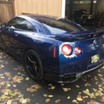
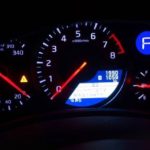
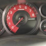
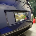
The GTR is back in the house. I picked it up from English Racing today so I can put some break in miles on it. Thanks to Myles Kerr, Sean Hart, Brad Ruth, Atif Awan, Lucas English, and the rest of the guys at English Racing for the incredible work.
As soon as I get the break in done, Timothy Bailey and I will get it on the dyno.
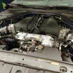
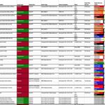
Oh and here is a list of what they did for me:
ER Ported Heads
with GSC Valve Guides, GSC S2 Billet Camshafts,
+1mm Superalloy Exhaust Valves, +1mm Intake Valves
Titanium Retainers + GSC 5054 Valve Springs
O-Ring Head Surface
ER 3.8L Large Rod Shortblock
New VR38DETT Case
Carrillo HD GTR Rods
CP-Carillio GTR Pistons with Upgrades DLC coated Pins
ETS Race Intercooler with TIAL BOVs
ETS Turbo Kit with 3.5 Inlets
Precision 5858 Turbochargers with Speed Sensors installed
Open Dump Downpipes
Record Dump Downpipes
T1 V2 Billet Harmonic Damper
T1 Air/Oil Separator
T1 V2 Fuel Rail Set – Black
T1 EGBP Damper Kit (x2)
T1 CNC Oil Pan
Injector Dynamics ID1050x Primary Injectors
Injector Dynamics ID1300 Secondary Injectors
Injector Dynamics ID750 Fuel Filter with Pressure/Temp Sensor
BoostLogic Dual Injector Intake Manifold, with Rails
Fore Innovations Triple 450lph E85+ Fuel Pumps + Fuel Lines
Visconti Secondary Injector Drivers
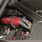
Pre Turbo, Post Turbo Pre IC, Post IC, Manifold Pressure and Sensor Transducers on both sides of the engine.
EGT and EGBP pre and post turbine, on both sides of the engine
Coolant and Crankcase pressure sensors
And the car already had (and still on the car):
Jacks Drag950 Transmission (18-plate clutch, billet 1-6 gears)
Cobb Midpipe
Legamax Exhaust
Gotboost Flex Fuel

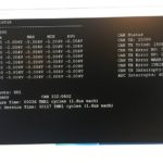

I did a little testing to verify the capture and CAN transmit times on this 40MHz dsPIC. Time for capturing all 8 analog channels is about 58us, and time for transmitting that data over a 1mbit CAN bus is about 130us.
I had no problem setting that capture and transmission rate to 1000hz (1ms), since I am under 20% interrupt time load.
For most uses cases I will be capturing at 1000hz, but using an FIR filter to decimate down to 100hz (or less), and then output over CAN at 100hz. It is pretty easy to make multiple FIR filters for different decimation rates per channel.
When I switch over to the QFP44 version of this controller I will certainly be able to capture all 13 analog inputs and send them over CAN.
Not bad for a microcontroller that is $3.


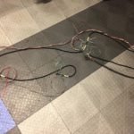
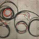

Since my GTR is getting close to completion, I need to get the sensor wire harnesses done. I used some rope and string to figure out the lengths and routing, then used that as a guide for each harness. Each sensor harness is twisted, and then the sensor harnesses are combined and twisted for each main harness.
Normally I would have combined the +5V and GND wires from each sensor in a given harness, but with so many sensors I will be connecting to a number of different capture devices. Each of those devices has their own +5V supply, and in the case of the Motec ECU there are 3 independent +5V busses.
I still need to add the larger connectors on the ECU side, but I’ll do that after a test fit.
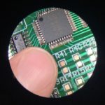


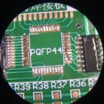
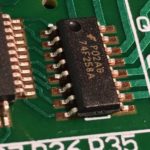
I took a crack at hand soldering those 0805s, 0603s, SOICs, and QFPs. It took me three tries on the second QFP to get it right. Fortunately the hot air rework tool makes removing them easy. In the end I got both QFPs down and tested every pin. The 0805s and 0603s were indeed pretty easy.. easier than I thought they would be.
Next up I’ll do another of the same board with solder paste and the air station, then another with a skillet, then repeat all three again. The mantis makes it really easy to see your screwups! (Also Matthew R. Wilson pointed out this practice board doesn’t have solder mask between the pins on the QFP, which makes it a tad harder)
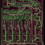


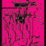
It is interesting to look at how the auto-routing performs in Diptrace. Attached are the following:
(1) My 2 layer hand routing, with as much ground plane fill on the back side as I could do. I tried to do as much of the routing as possible on the topside so the ground fill would cover as many things as possible.
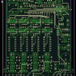
(2) The auto-routed 2 layer which doesn’t have any planes. The autorouter uses a pretty simple layer direction method, with more traces on the lower layer than the upper one.
(3) The auto-routed 4 layer with a ground plane fill on one inner layer, and a power fill (both 3.3V and 5V, with the 3.3V parts on the upper part) on the second inner plane. After adding the fills I let the auto-router do the rest.


For doing fine PCB work I picked up a Vision Optics Mantis. (3D microscope). It is a really nifty device with a single large ‘viewport’ instead of eyepieces. It gives you a very stereoscopic view that you can pan and tilt around.
Optically it appears like large objects at a reasonable distance, so I can wear my regular long range vision glasses and things are in perfect focus. Neat technology. (I don’t know Paul Yaw, you might just have to get one).

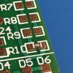

Ok hand soldering 0805s I can see, but those 0603s are tiny! I clearly need something with stereoscopic magnification.


Well, it worked. Sort of. I did a second pass moving the components around and I was able to hand route in two layers, with most of the second layer being a ground pour. I still need to do some trace cleanup, but DRC passes so tolerances are ok. Certainly it is good enough for a prototype.


This was perhaps the most interesting drink I have tasted this year. A port from 1875. It is hard to imagine drinking from a bottle made in not the previous century, but the one before that.
It was actually pretty good. A bit sweet, and the port from 1970 was actually better, but the history of a bottle this old!
Happy Thanksgiving everyone!