Rasp Zero
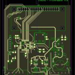
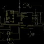
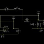
I took a crack at making a board layout using a Raspberry PI Zero as well as a dsPIC33 microcontroller that has two hardware CAN bus interfaces. This allows all of the CAN capture and decoding to occur in the micro, as well as filtering and cross bus processing. The dsPIC is connected to the PIZero over SPI (10MHz), which provides the queuing needed for high transfer rates while logging.
One of the goals of this board was to not only support logging of data from other CAN devices but also the ability to drive other displays and dashes. I routed 4 ‘flexible’ pins from the microcontroller to the connector, as well as 4 from the Raspberry PI. The microcontroller ones can be assigned to be SPI, i2C, UART, and other generic GPIO functions. The pins from the PI are also SPI, i2C, or UART capable. That provides a ton of extra flexibility depending on how you want to use them.
This particular dsPIC has a split flash feature which makes it easy to support firmware upgrades directly from the PI Zero.
The component costs are low, probably $20 plus $10 for the raspberry pi zero W.
Since the PI Zero W has wireless built in, configuration over a simple web interface will be easy to implement, as well as things like auto upload or auto email of log files, etc.
This could also be useful for some bus reverse engineering, as you have a good combination of 2 CAN buses with enough speed to do cross bus replication (so you can be a MITM of a device), plus some analog and digital inputs to help correlate things, all over a simple web interface.
I used a mixture of surface mount and through hole stuff as this is a prototype and I already have a bunch of the through hole parts sitting here. For the final rev I will switch most of that stuff over to surface mount.


