ADC
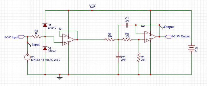
Fellow data nerds – Just looking to see if there is anything obvious I am missing. This is the analog input stage for my 24 channel ADC to CAN device. This is from a Spice simulation, so V1 represents the 5V supply, and V5 a simulated 0-5 signal. Here is my thinking: R1 is a current limiting resistor for the two Schottky diodes. They will conduct if the input voltage is over 5.3V or below -0.3Vs. That provides basic input protection ( hooking input to 12Vs, etc). U1 is an isolation op-amp to provide high input impedance. R4,R5,C1, and C2 make up a Sallen-Key filter, and R4,R5, and R3 make up a voltage divider. Combined with U2 this gives a 2:1 voltage division, and provides output impedance isolation to the ADC. The filter is set for a 3db rolloff around 2khz, which is good considering I only need to support 1khz sampling. For an Op Amp I need to use a single supply rail-rail variety like an OPA342. Since you can get those in 4x packages, I could do two input channels per chip. Let me know if it looks like I missed anything obvious.
